

Unified Modeling Language UML
As an object-oriented analysis and design modeling language, UML (Unified Modeling Language) combines a variety of technical methods. With the help of UML, analysis and design can be smooth and easy.
History of UML
From late 1980 to 1994, there was many advocates of object-oriented design methodology. The following methodologies are the representatives.
- Method of Mr. Schlehr and Mr. Mellor who published the book "Object-Oriented Systems Analysis"
- Method of Mr. Booch who becomes famous for Ada Design
- OMT (Object Modeling Technique) developed by Rumbaugh of General Electric Company
- OOSE (Object-Oriented Software Engineering) proposed by Mr. Jacobson who is good at requirement analysis with cases
- The so-called second-generation methodology "Fusion" developed by Hewlett-Packard Company that combines many advantages of other methods
- Mr. Coad and Mr. Yourdon's OOA (Analysis) / OOD (Design) method
In the year 1994, Mr. Booch and Mr. Rumbaugh began the study of unified methodology in Rational Software Company. At that time, Mr. Rumbaugh had obtained the No.1 position with his own methodology OMT, but he stepped forward again towards a unified method together with Booch. In 1995, Mr. Jacobson joined their union and in July, 1996, the UML0.9 was finally released. In January, 1997, UML partner organizations completed UML1.0. UML partner organizations includes DEC, HP, I-Logix, Intellicorp, IBM, Icon Computing, MCI Systemhouse, Microsoft, Oracle, Rational Software, TI, Unisys and other companies. At that period of time, four goals are set for UML.
- Adopt object-oriented concepts to model the system (not limited to software).
- Clearly establish the contacts with upper works or achievements which can be operated.
- Avoid escaping from complex and mission-critical systems and be able to cope with issues concerning the scale of system.
- Develop a modeling language which can be recognized and adopted by both human and computer.
(Ref.: "UML Summary" published by Japanese Rational Software Ltd.)
Features of UML
UML contains the systems development phases from requirements analysis to system analysis, design and testing. The adoption of diagram is extended from Mr. Rumbaugh's OMT, Booch method, Mr. Jacobson's OOSE and other methods. The objects include information systems, modular real-time systems, distributed systems, business systems, etc. The following diagrams are defined in UML.
- Usecase Diagram
- Class Diagram
- Package
- Collaboration Diagram
- State Diagram
- Interface
- Sequence Diagram
Application Design and Modeling
What is the application design? In short, it is program processing and data structure analysis.
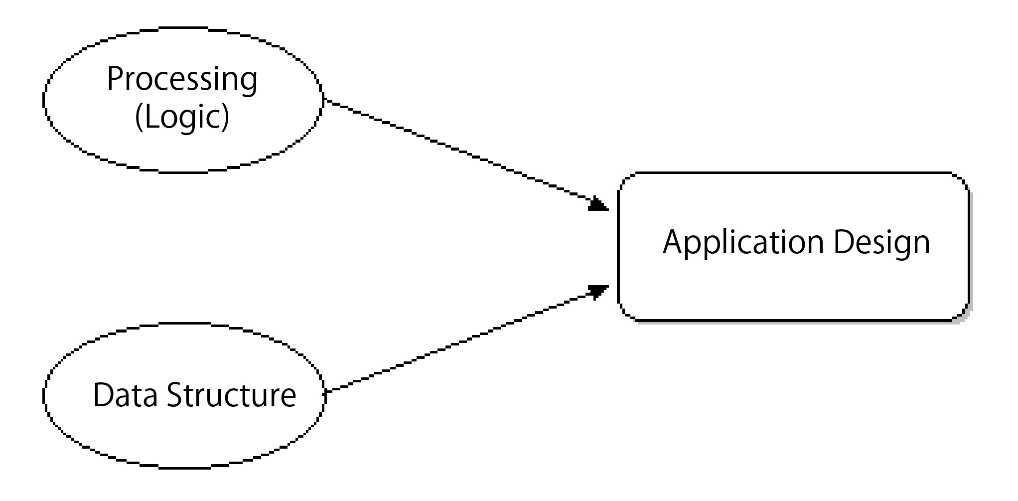
There are two aspects in the application known as processing logic and data processing. In all application designs, just like the data-centralized design (DOA), the data structure deserves more attention than the processing itself. Processing tasks are separated from the data and turned into single programs. When changes are necessary, since the rewriting of processing program is very easy, they tend to become disposable programs.
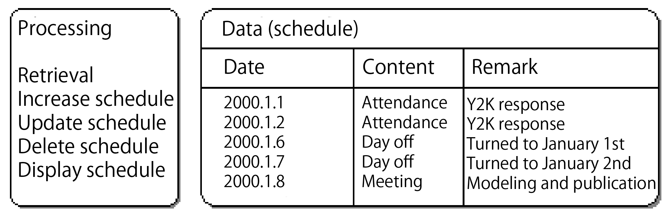
Here let's see an example of travel management program. This program is very simple. After you enter your own travel plan, you just need to click "search" and the results will be displayed. The travel plan is displayed as "January 1st, 2000: solve Y2K failures". In addition, the functions include inserting and deleting of the travel plan. As shown in Figure 2, "processing" and "data" can be separated. In this way, we can study the "processing" and "data" respectively in the application design.
History of Application Design Method
Here we briefly review the history of the application design methodology. In the year 1980, system engineers must master the structured approach known as SA / SD (Structured Analysis / Structured Design). This method adopts data structure diagram showing DFD (Data Flow Diagram) and ER (Entity Relationship Diagram) . DFD is researched by Mr. DeMarco and others. Mr. James Martin built the information system from a business perspective, further extending the IE (Information Engineering).
Now, DFD is more than a simple set of programs. It is often used to organize the necessary business processes in the operation. It is adopted in some projects which are above the level of system design. Besides, ER diagram is also widely used in the design of a relational database. Compared with the traditional method, the recent emerged object-oriented methods which can simultaneously respond to data and processing gradually become the mainstream. In programming languages, COBOL is gradually substituted by Java or Web language. However, in object-oriented design, as long as the mainstream of database is the relational database, we must first understand the ER diagram.
Design Steps
System design can be divided into three steps as "requirements specifications", "System Analysis" and "System Design". "Requirement specifications" will decide the application system. "System analysis" will decide functions of the system. It is also known as design theory. Here, we will not take the actual application system into consideration. It's only a simply and theoretical design. Correspondingly, "system design" is the design considering the assembly. The so-called assembly refers to the use of Web application system or the adoption of Java language. System design is also known as physical design. For example in Oracle, it is something like deciding on the increase of a table, etc.
Here let's see the relationship between the design phases and design diagram. If the technologies used in all stages are object-oriented, we may directly adopt the subject-UML here. But in fact, it's hard for all the technologies to be object-oriented. For instance, when relational database like Oracle is adopted in data management, the use of ER diagram in this design will be more suitable. When Java is used as a programming language, we will not adopt the structured methods, but the object-oriented design methods. Therefore, the engineers must have the ability to respond flexibly according to different situations. Correctly understand the relationship between object-oriented methods like UML and DFD, ER diagrams.
Structured Methods and Object-orientation
Before the introduction of object-oriented design methods, we should first learn about structured methods. The DFD as shown in Figure 3 represents a flow of processing and data. Here, the "Search travel plan" is the processing; the input is "date"; and the output is "travel plan". In DFD, the program (processing) is represented by ellipses; the data flow is indicated by arrows; the storage location of data is shown by lines. The adoption of DFD can layer the processing. The more detailed processing is shown in Figure 4 with the following diagrams (the hierarchical relationship is represented like 1 - 1.1, 1.2).
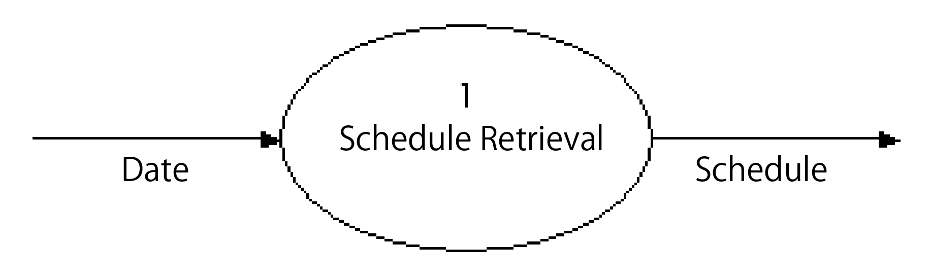
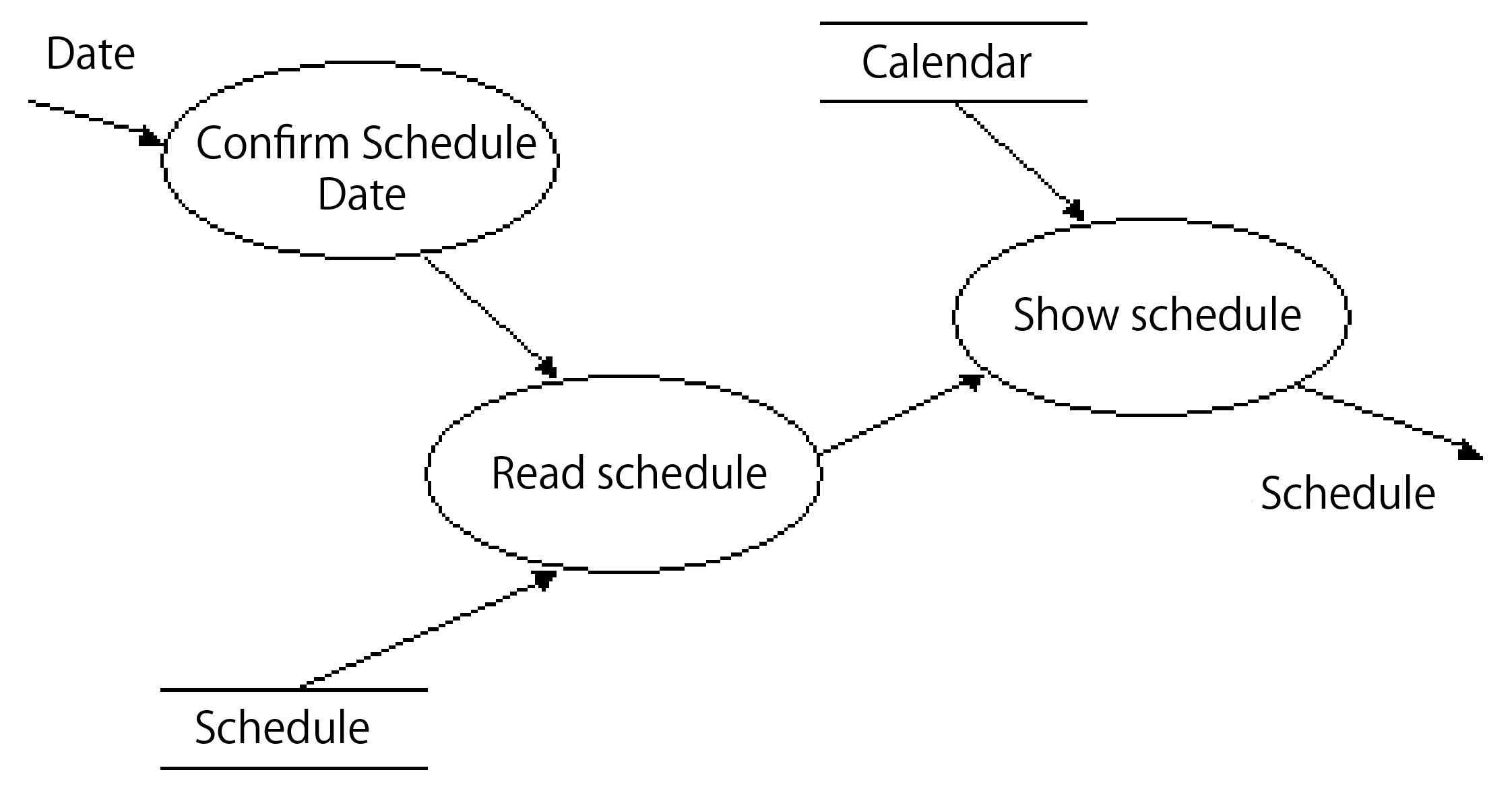
Figure 4 shows the processing of "Search travel plan" in the form of DFD. First enter the date you want to search. Then use the following program "Read travel plan" to read the data from the "travel plan". Subsequently, the data is combined with the "Calendar" and presented together.
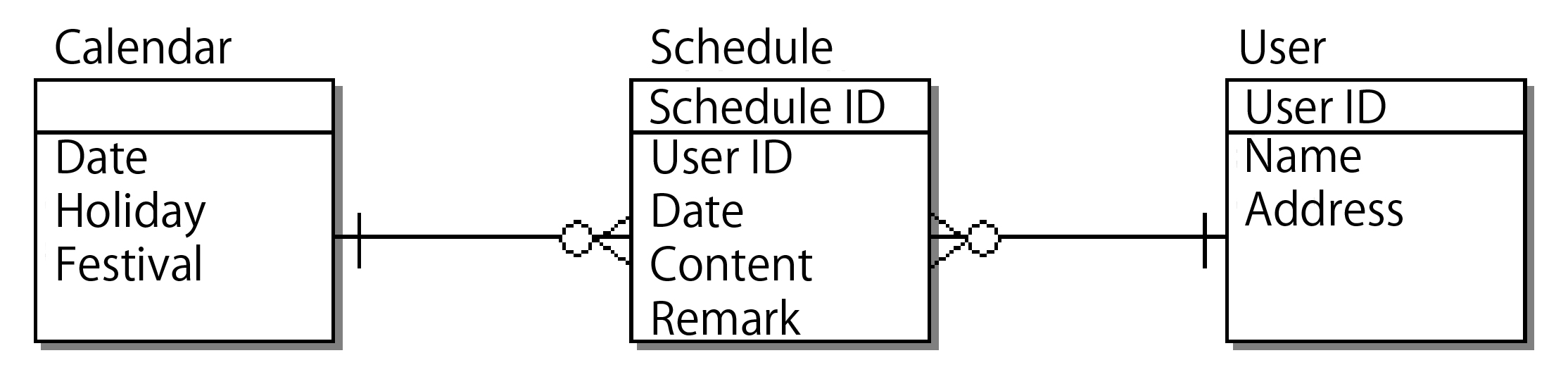
Next, let's see the ER diagram. The ER diagram shown in Figure 5 represents the data structure in the travel management. Here, in order to make the program available to multiple users, an entity called "user" is established. Entity refers to the storage location of the data, equivalent to RDB tables. Then, the saved contents are call attributes. In this example, the "travel plan", "user" and "calendar" are part of the data. And the "date", "holiday" and "activity" are the attributes of the calendar.
Why choose object-oriented design methods?
In such ER diagrams, the system is displayed simply and clearly. So why not continue to use it? The main reason is that the assembly environment is easy to bring huge changes to Java, C + +, CORBA, EJB and other distributed objects. Once the programming language or development environment changes, the old design technology will not be enough for the processing. The popularity of structured methods indicates the booming of structured programming. This assumption tries to avoid "spaghetti" code, GOTO statement. Instead, it advocates the adoption of structured code for programming. Then this idea is applied to the design level, because huge changes like structurization have also taken place here. Once the development environment is changed, the design methods should also be changed. Once we want to use Java or Web technologies to build the system, we need the object-oriented design. With the help of object-oriented modeling, we will be able to closely link all phases, from the design phase to the development phase, together. For example, DFD can not be used in program design, but it can use object-oriented class diagram. We can use CASE tool class diagrams to generate the code.
On the other hand, structured methods are hard to respond flexibly to the changing requirements of the system. The data structure can be managed unitarily through ER diagram, but since the processing methods are programmed into the program, the processing logic becomes very scattered. In object-orientation, since data and processing are integrated, even if the data structure is changed, the corresponding processing can be changed immediately. In addition, the structure of customer / server system introduces the application browser and becomes a structure with three levels. If we separate the data and process of design with structured methods, it will be hard to separate the assembled data and the browser accurately.
Through the above description, you may feel that the object-oriented design is very difficult, but in fact not. Modeling will be easier with the adoption of object-oriented design than with structured methods. For example, in shipping and receiving systems, an entity called "order" may appear at any time during data modeling. It is easy to be called to mind by experienced modeling engineers, but those engineers with little experience is hard to think of it. In contrast, in the object-oriented design, after the study of specific case-script, necessary elements can be selected in a sequential manner. This should be relatively easy for the beginners.