

Component-based Development with Catalytic Method
Catalysis method is a methodology proposed by Desmond D'Souza of ICON Computing Company and Alan Cameron Wills of Trireme Company. As a member of the UML organization, D'Souza participated in the UML proposal held by OMG. At the same time, he also participated in a variety of activities as a contributor to UML. Catalytic method adopts component-oriented and framework-oriented methodology, able to cope with large-scale business systems. Furthermore, if the system assembly adopts distributed object technology CORBA or DCOM, the entire process from design to assembly can be accurately handled. Of course, due to the adoption of UML labeling method, you will be able to understand the diagrams in catalytic methods once you grasp the knowledge of UML.
The so-called component
When we encounter the word "Component", we may think of Microsoft's DCOM (Distributed Component Object Model) or OMG's CORBA (Common Object Request Broker Architecture). These are assembly techniques rather than design. Here, we will give a brief introduction about "What is a component".Component refers to the combination of several objects (sometimes only one) or wide-range matters like applications. The purpose of component is to add some plugs & players (like computer hardware) and other functions into the application. In order to insert plugs, players and other components, there must be some interfaces. Therefore, interface is very important in the design and development of components.
For example in Figure 1, the "engine" is linked to other components through the interface.
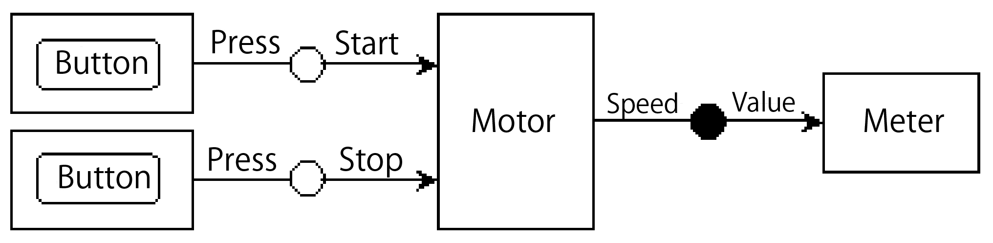
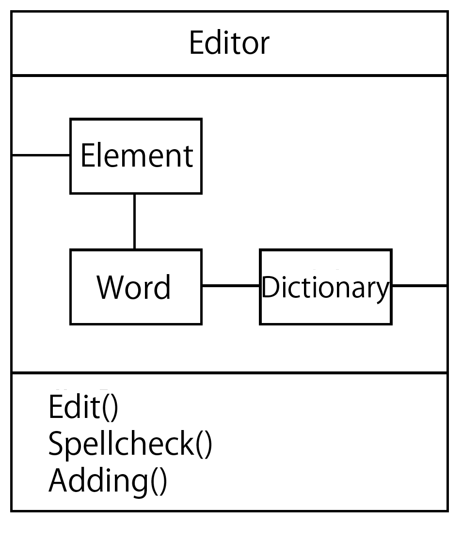
It is not simple for the engine to send speed data to the meter. This action may be divided into several commands. We get an interface when we combine all of them together. Sometimes, there may be a plurality of interfaces like engines. We will give another example of the component. Let's see the component "Edit", which includes "word" and other objects serving as the internal data.
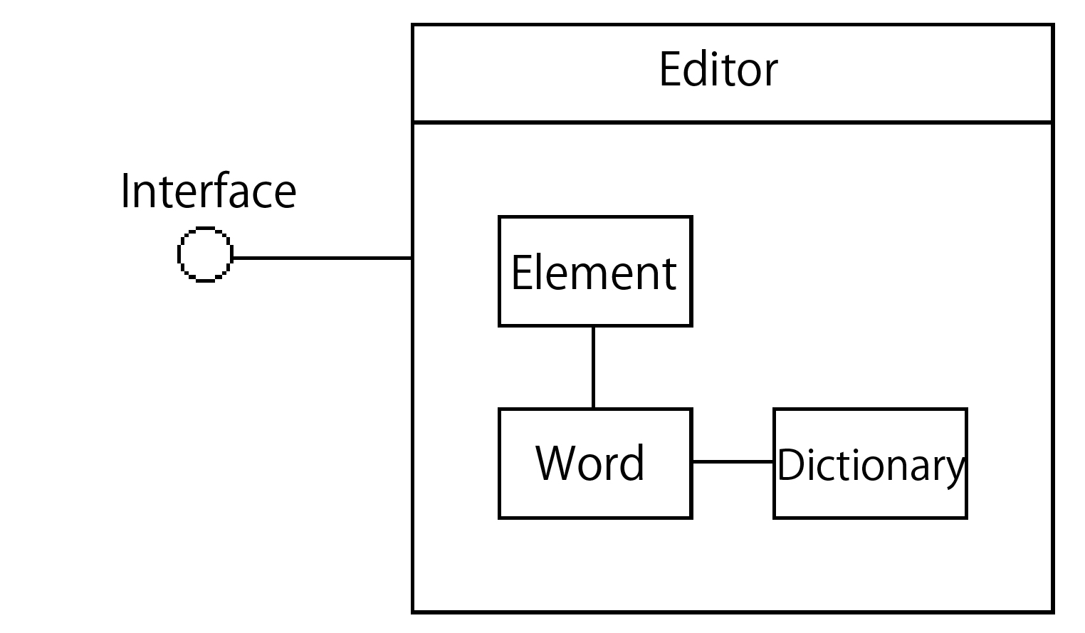
When we insert "Edit" into other applications, the operation will be led out through this interface. In component development, it can be inserted into drawing software, Web browser and other applications. From the aspect of application, we can choose among several editing components.
Here let's see the assembled environment using components, i.e. distributed objects. DCOM and CORBA are both representatives of distributed objects. Others include Java's RMI (Remote Method Invocation), HORB, etc. In object-oriented application development, the objects are linked to the applications in static or dynamic form. There will be no problem if the operation is done on one machine. However, when the system is constituted on multiple machines online like the decentralized system, a very complicated structure is needed because of the need for remote access to online object.
The so-called interface
As for the example in Figure 1, let's see the interface on the following Java program. The "meter" class can be assembled as shown below.
					interface SpeedMeter

					{

					    int   start();

					    int   send(int value)

					    int   stop();

					}


					class ConcreteMeter implements SpeedMeter

					{

					    // Code assembly

					}
In this way, we can define the operations start(), send(int value), and stop() for interface SpeedMeter. Then implements SpeedMeter can be realized for ConcreteMeter class.
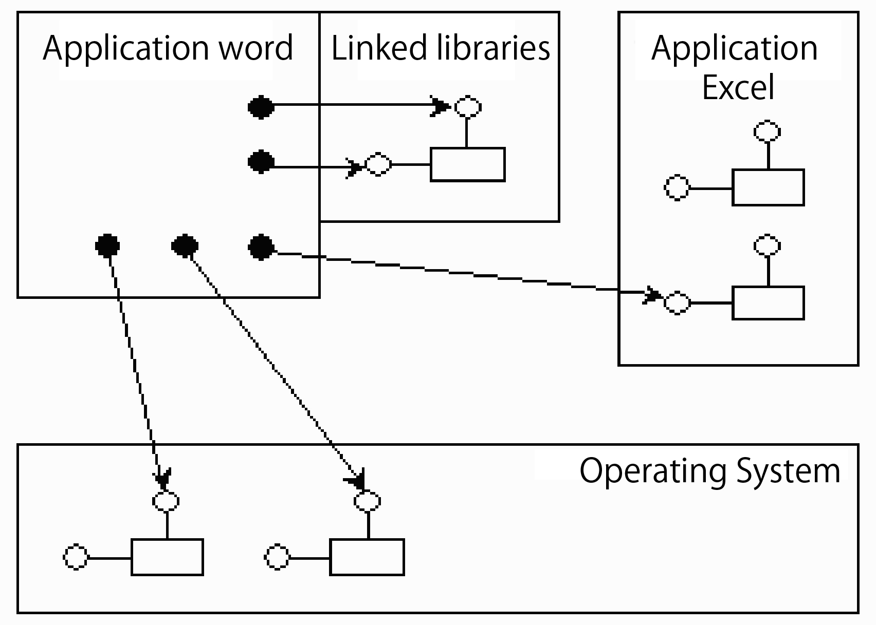
In addition, Microsoft's DCOM structure is adopted for simple confirmation. As shown in Figure 3, the application contains the object, and the object is opening the interface as an external visiting window. For example, if you want to use the "word" to get the excel spreadsheet, you only need to call out the "excel" interface installed in "word".
UML component labeling method
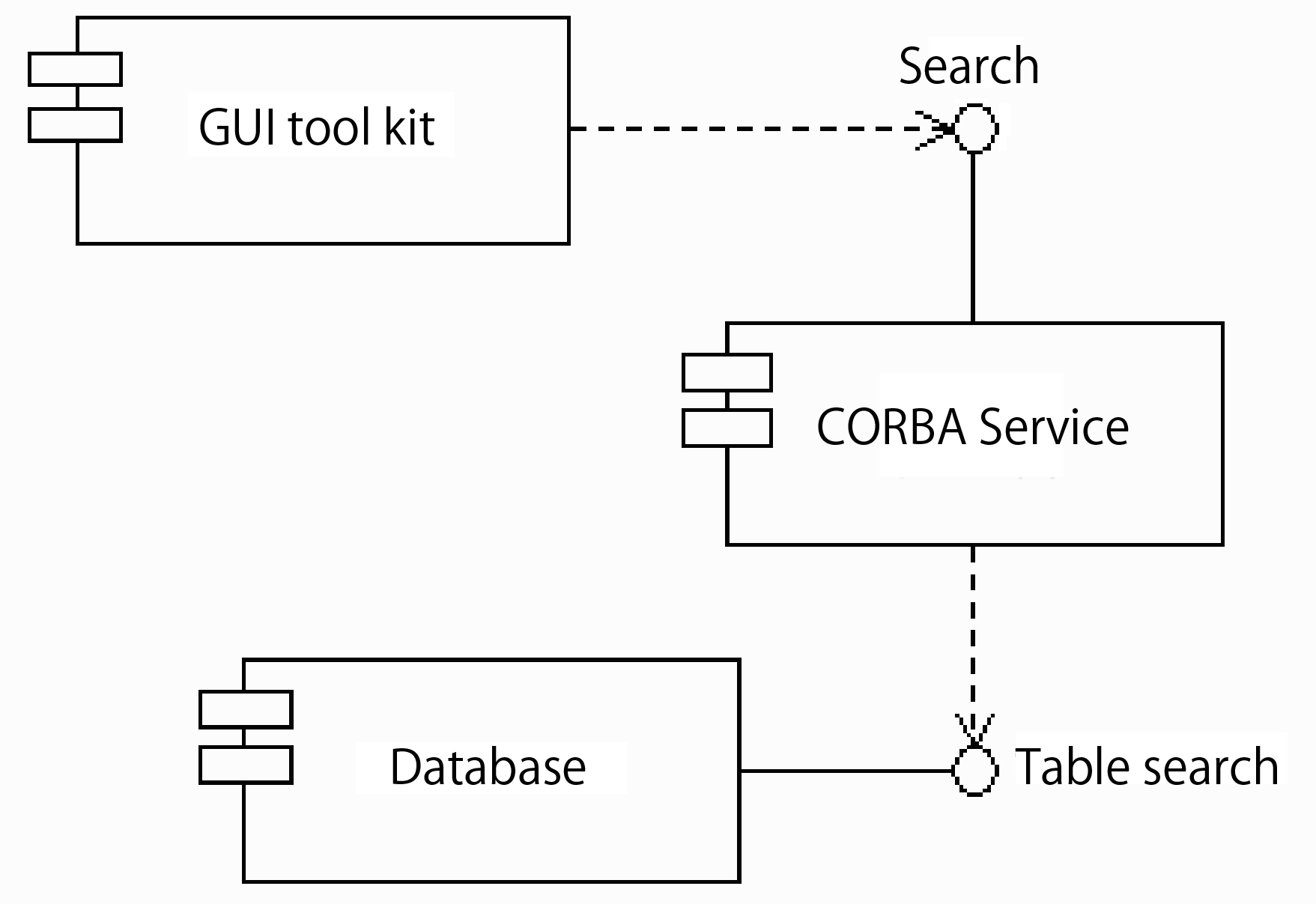
Then let's turn to UML labeling method. In UML, there are assembly diagrams showing the components. Here let's try one of the component diagrams. Figure 4 shows that the "Database" component contains a "table search" interface, which is led out by the "CORBA Service".
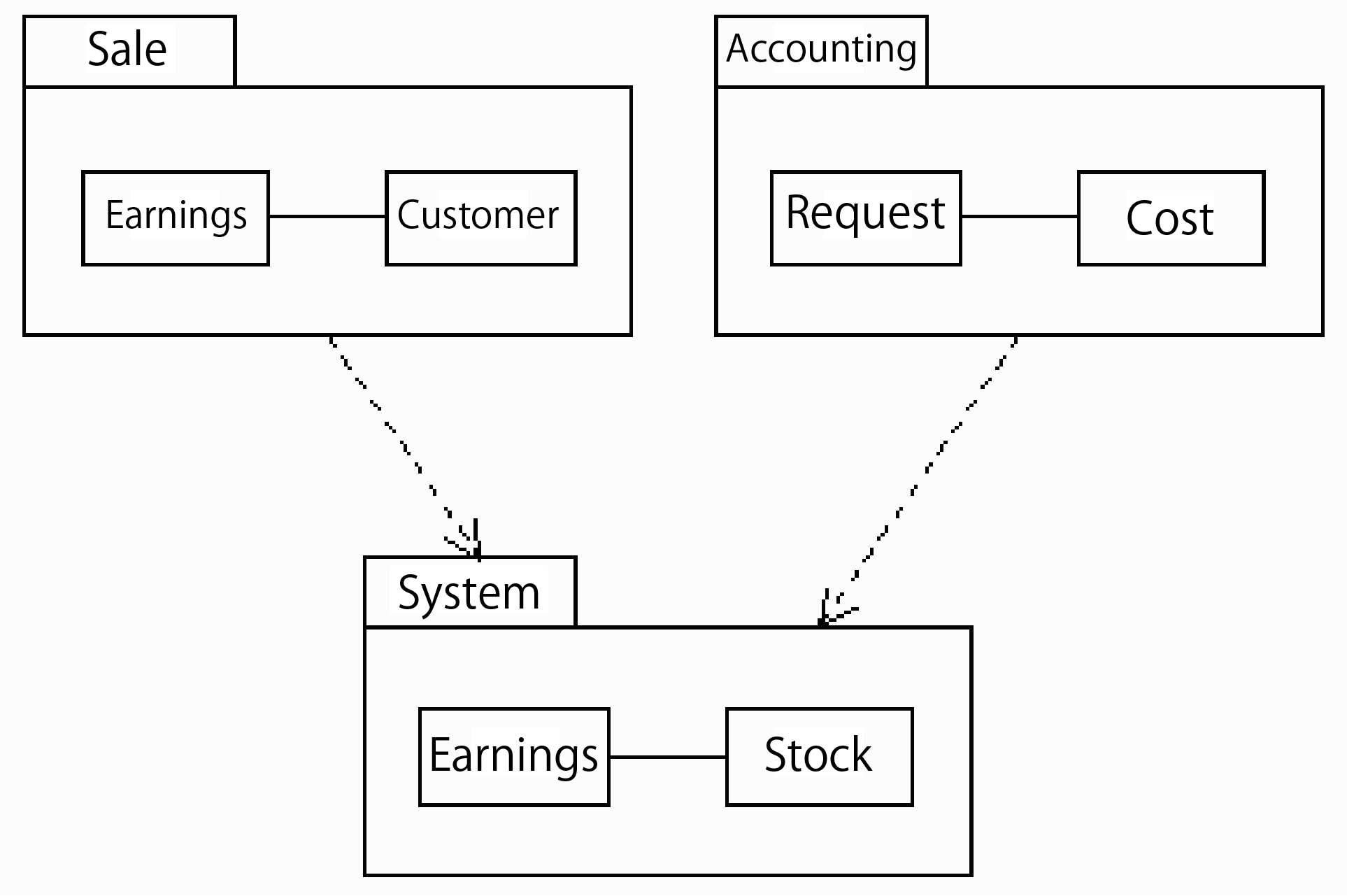
Up to this point, we have explained the knowledge of assembly, but the component technology includes not only assembly. There is a component during the analysis and design phases, i.e. the business component. Business component, previously known as business object, is becoming increasingly important. Since the increase of object quantity will make the management of unit object more difficult, it is recommended that the unit components are classified into groups for management.
"Sale", "Accounting" and some other functions in Figure 5 were previously treated as sub-systems. But if we treat them as components from the beginning of the design stage, we will be able to conduct the design of plugs & players. These components contain object-oriented analysis and design models. The recycling of models can be achieved through access to these component classes from the target system.
The so-called framework
Next, we will give a brief introduction of an important factor in object technology - framework. Framework means when the application structure is completed, new applications can be generated through modification of part of the contents. Let's see an example of framework - a Java applet. The Java applet contains operable frameworks, which include methods like "init()", "run()", "start()", "stop()", etc. Programmers can generate new applications simply by modifying these methods. This is an example on the assembly level. On the design level, the framework is called "model framework".
The so-called catalytic method
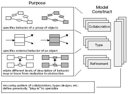
Catalytic method is a way of developing component-based applications. Extended UML labeling method is adopted. The advocates include Alan Wills and Desmond D'Souza. The biggest feature of this method is the component-based representation method. As shown in Figure 6, we can write down the interface operation on the bottom line, and then conduct modeling within the components. As for those connected with the external component, we can use a line to connect it with the component frame.
Catalytic method includes "cooperation", "type", "modification", "framework" and other concepts. Arrange the behavior of object group in the "cooperation"; decide the external behavior of object in the "type"; abstract the behavior and others in the "modification". After that, generate the plug-in type framework. In catalytic method, the level of abstraction of the objects is called the type. Functions between the types are called the behavior. This is equivalent to the cases in UML.
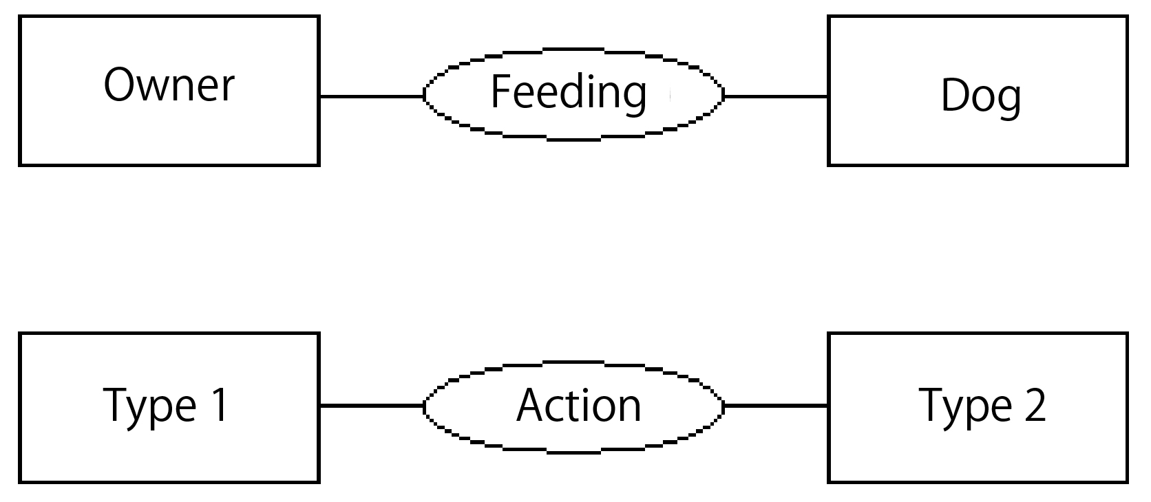
Let's see an example of behavior. There is behavior called "feeding" between the "dog" and the "pet owner". Figure 9 shows this relationship. The kind of relationship between the types is called "cooperation".
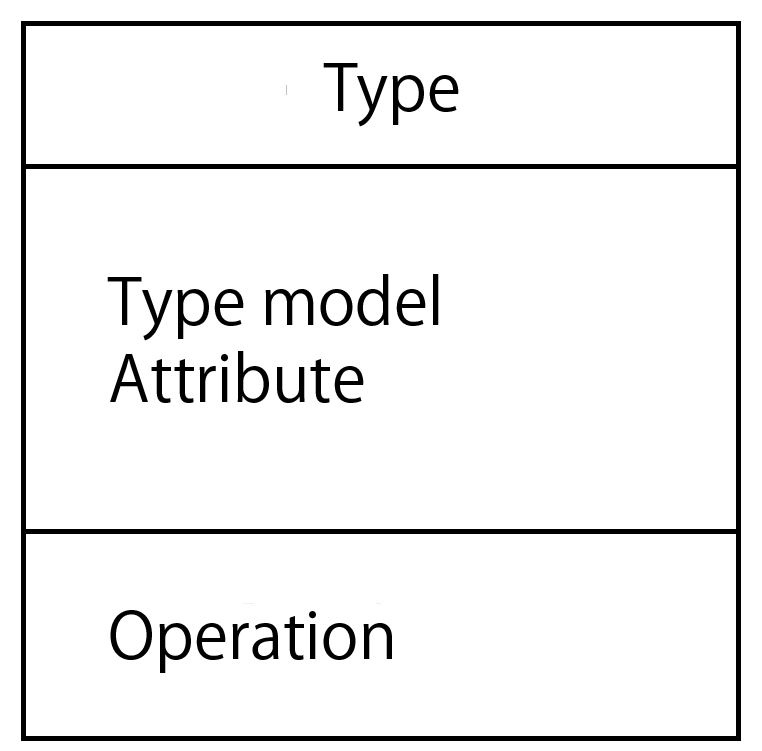
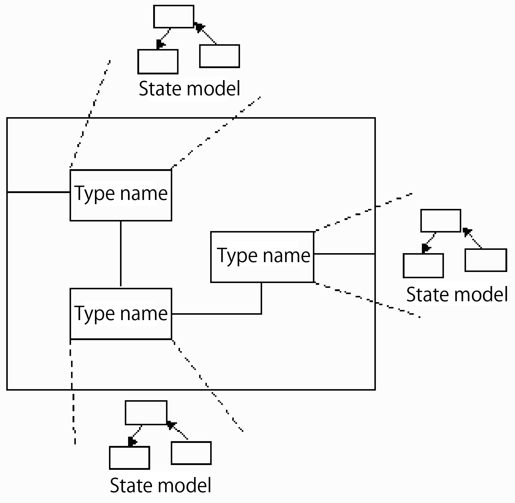
Type refers to the level of abstraction of objects or grouped objects. This is very similar to the entity or class in the data-centralized design method. The labeling method for type is to extend the UML class diagram. As shown in Figure 9, the above one is the type name; the middle one is the attribute or model diagram; the nether one is type-related operations. Operation is the behavior generated by the external of type.
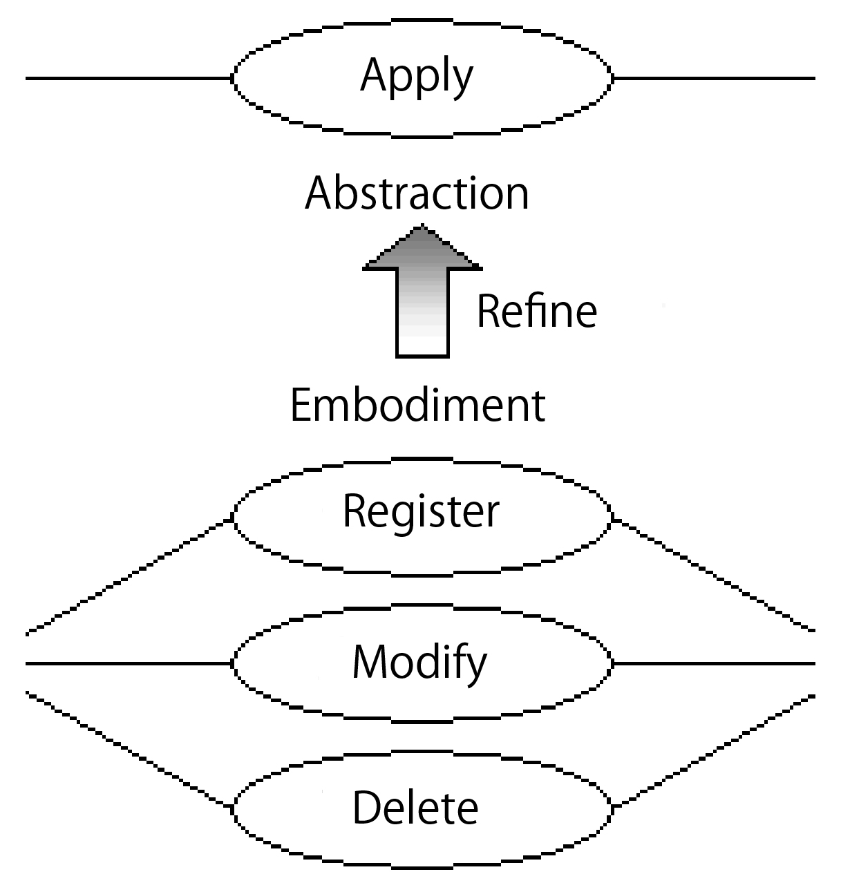
Catalytic method contains abstract levels like modification. Therefore, it can clearly indicate the drawing process from concrete to abstract. In the example of Figure 10, modification is done for behavior like "apply", "register", "modify", "delete", etc.
Modeling based on catalytic method
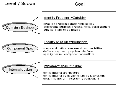
The development process of catalytic method is divided into three modeling process as shown in Figure 11. The first process is "business scope" which aims at clarifying business procedures and other processes. The second process is "component pattern" which focuses on minifying systemized object-event and then analyzing relevant factors. The third process is "internal design" which targets at analyzing the inside of the event.
Domain / Business
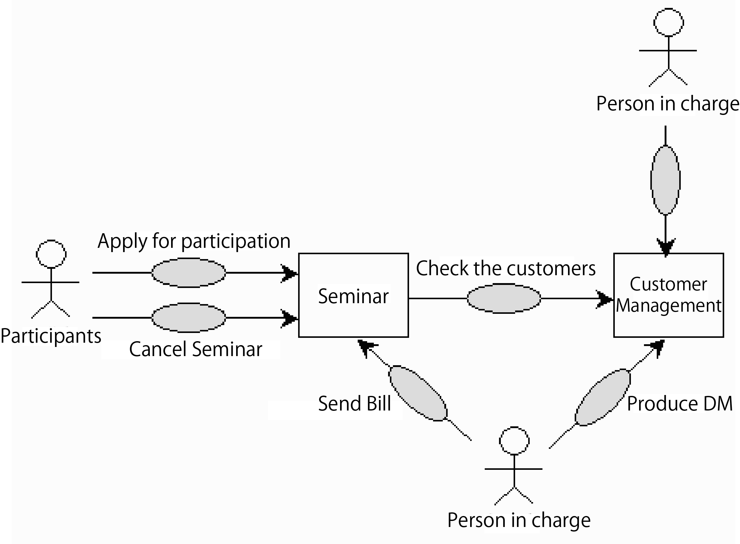
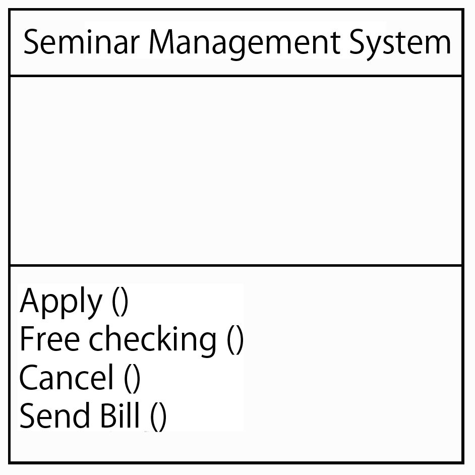
Here let's see the seminar management system. As shown in Figure 12 in the form of case diagram, the students apply for the seminar .
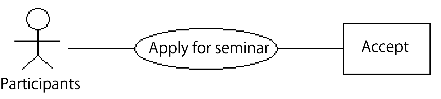
The students apply for the seminar. In UML, as external factors of the system, the students serve as the participants and are marked by human symbols. At the same time, the function - "apply for the seminar" is called the "case" and marked by oval shape. We can get the overall business process in Figure 13 with the application of above mentioned method.
Component pattern
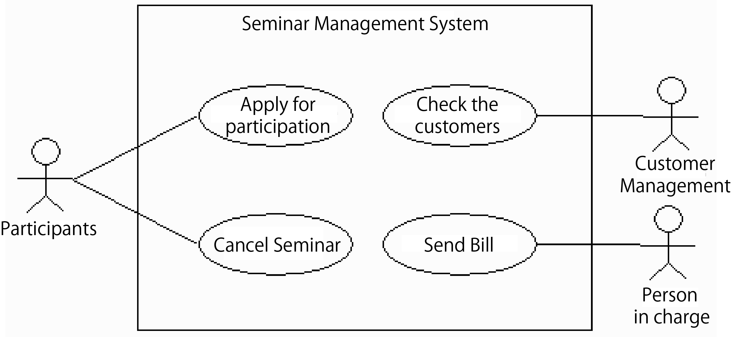
In Domain / Business modeling, the scope of systemization can be determined after the arrangement of overall summary. For example, we can determine the scope of the system as shown in Figure 14. Here, since the "customer management" belongs to other systems, it is deemed as a participant.
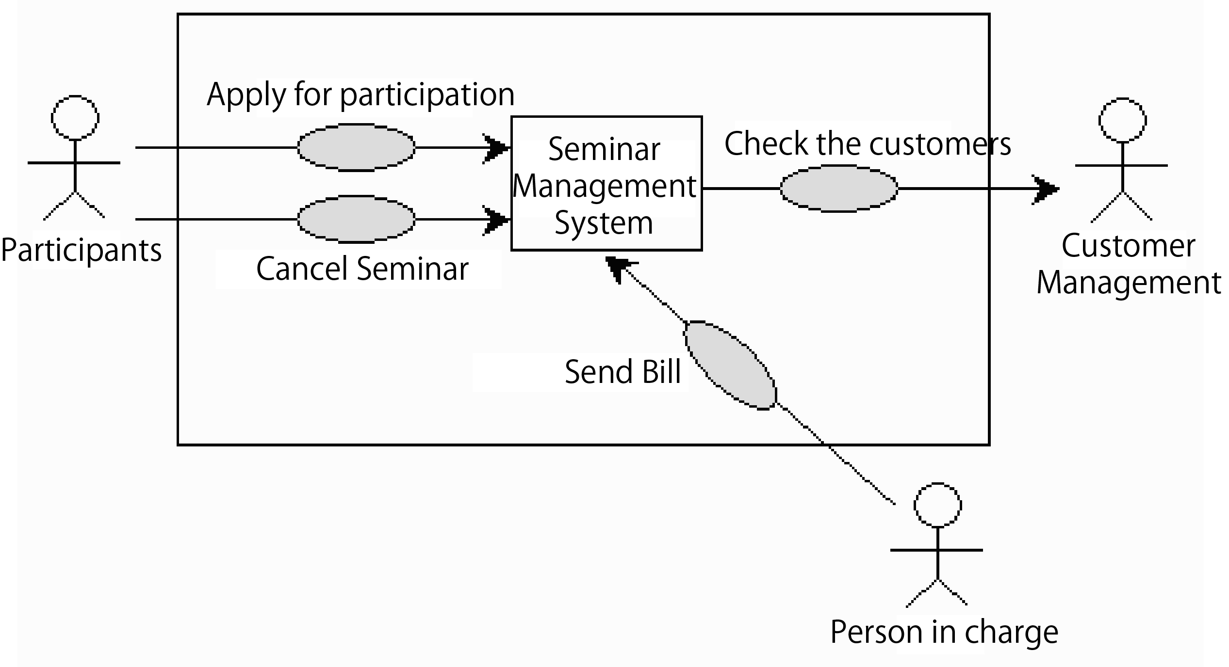
If we adapt Figure 14 into the UML case diagram, we can see it as Figure 15.
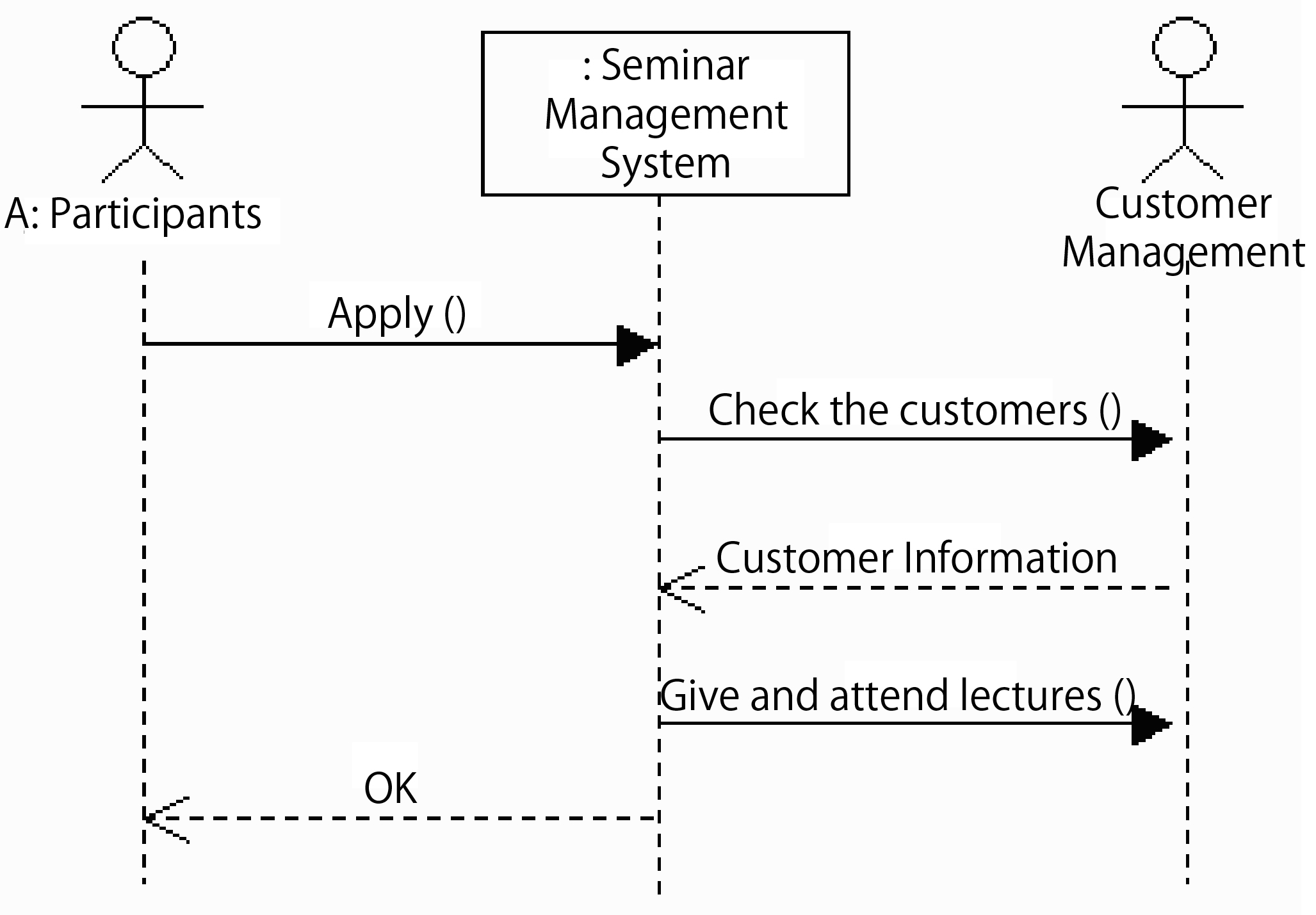
Therefore, we can determine the events of the system. Next, we can regard the system itself as a component and pay close attention to its input and output. This is equivalent to the communication in the case diagram. In order to generate the diagram accurately, we should adopt the sequence diagram. Thus, specific events like the scripts are generated, and each script is made into sequence diagram. In Figure 16, we import the operation "request ()" and get the events in Figure 17.
Internal Design
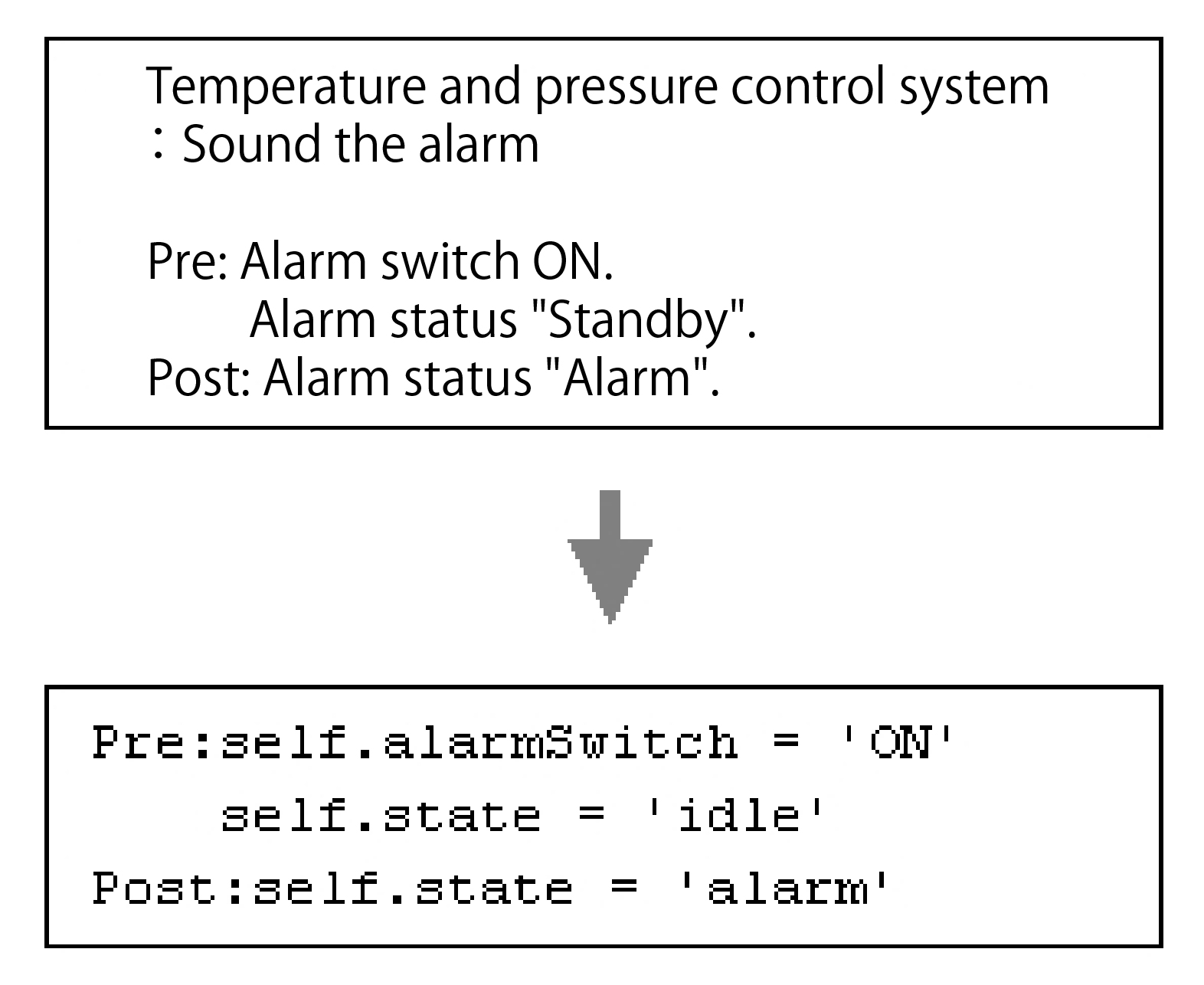
In the internal design, we should analyze the events imported in the last stage and then describe them in detail. This is represented by "Constraint". The language describing the "constraints" is OCL (Object Constraint Language). OCL is part of the UML, originally developed by IBM as the business modeling language in the Insurance division. The sentence structure of "constraints" is shown in Figure 18.
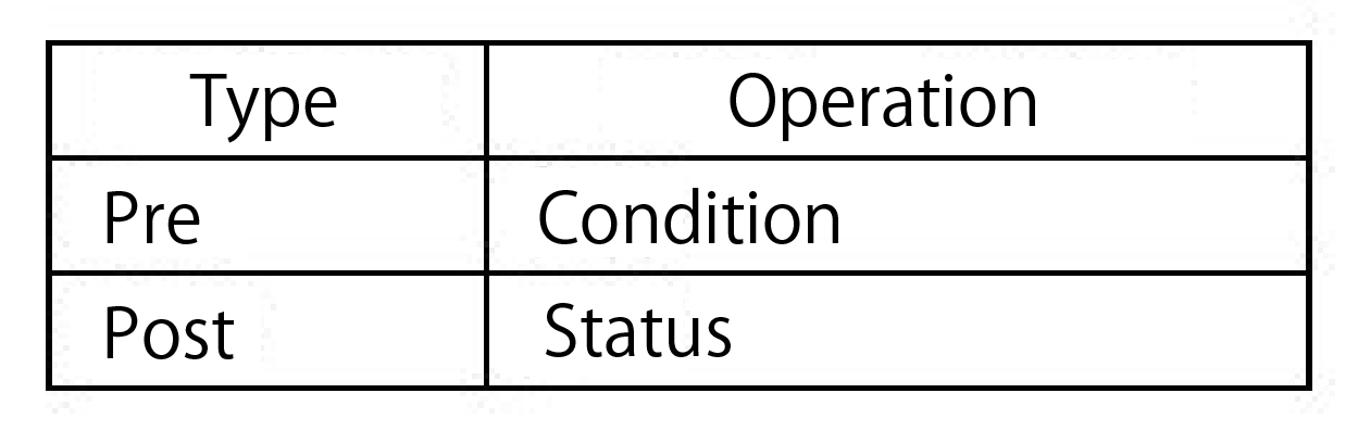
"Pre" refers to the Pre-condition, which the condition of triggering the operation. "Post" refers to the Post-condition, which is the result of the operation. In addition, since OCL is a modeling language, it's operational logic is hard to be described in detail. As for the description of logic, the behavior language has been proposed in OMG. (OCL specifications can be obtained in OMG(Object Management Group))
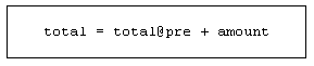
In addition, it can also be displayed in the form of calculation formula as Figure 20. @Pre refers to the period before the operation.
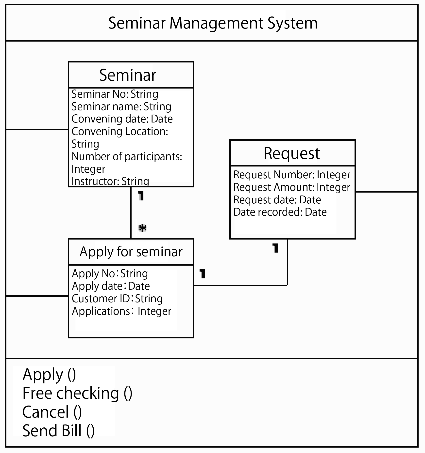
Next, let's go to the data structure analysis. This is similar to the ER diagram in the data-centralized design. However, it is not an "entity" but a "type" in the catalytic method. In addition, the "class" is used to assemble this "type". The finished type model is shown in Figure 21.
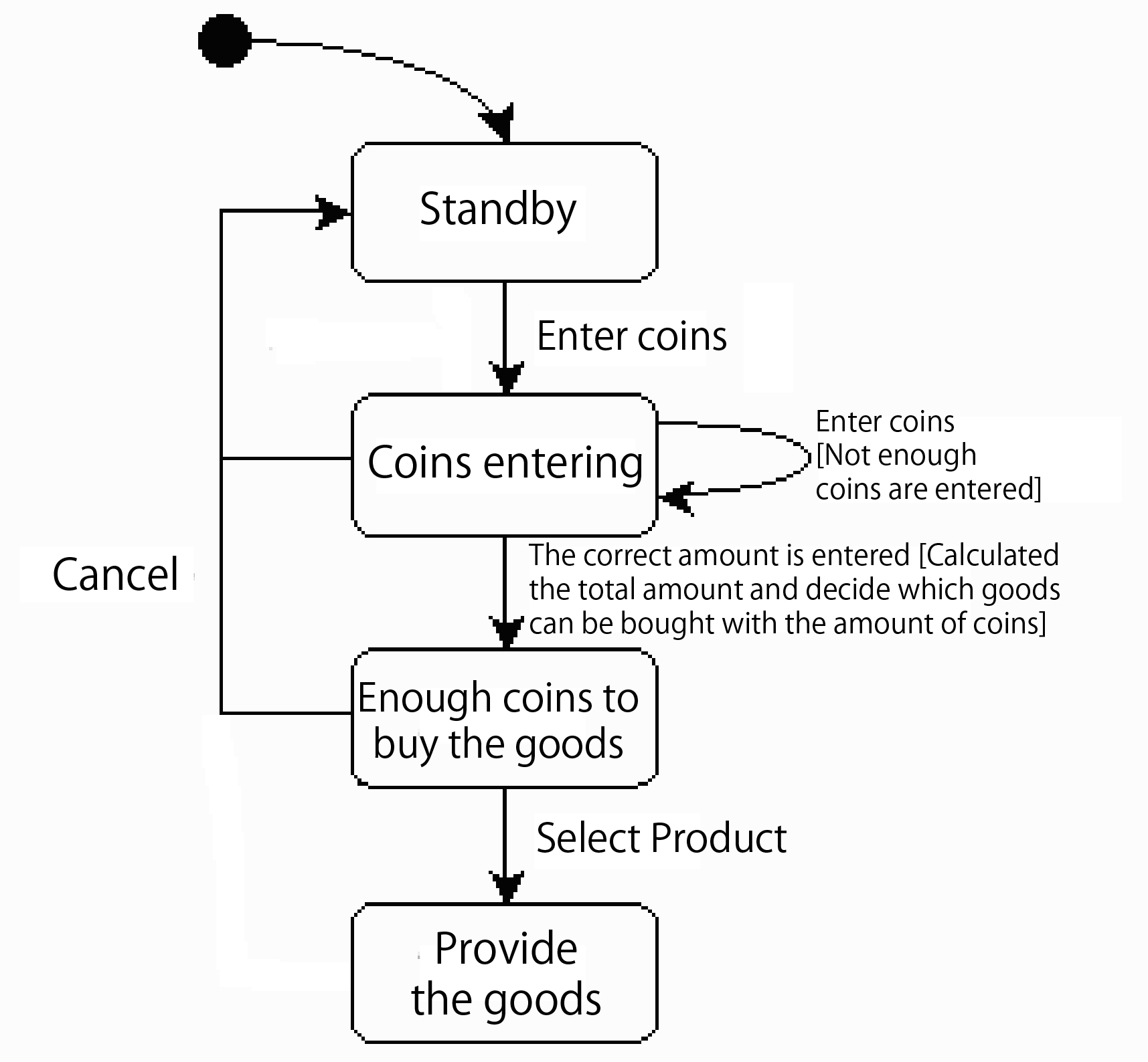
Further model the dynamic part - "state" - of the type. Here we adopt the UML state diagram. As shown in Figure 22, the state is made respectively for each type. Figure 23 shows an example of a state diagram.
Component design
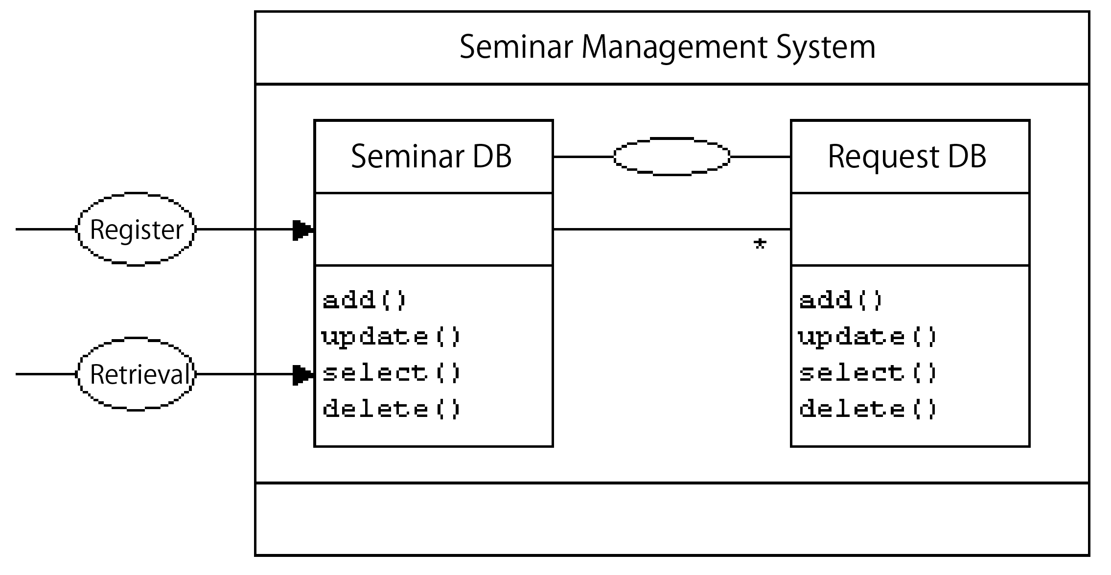
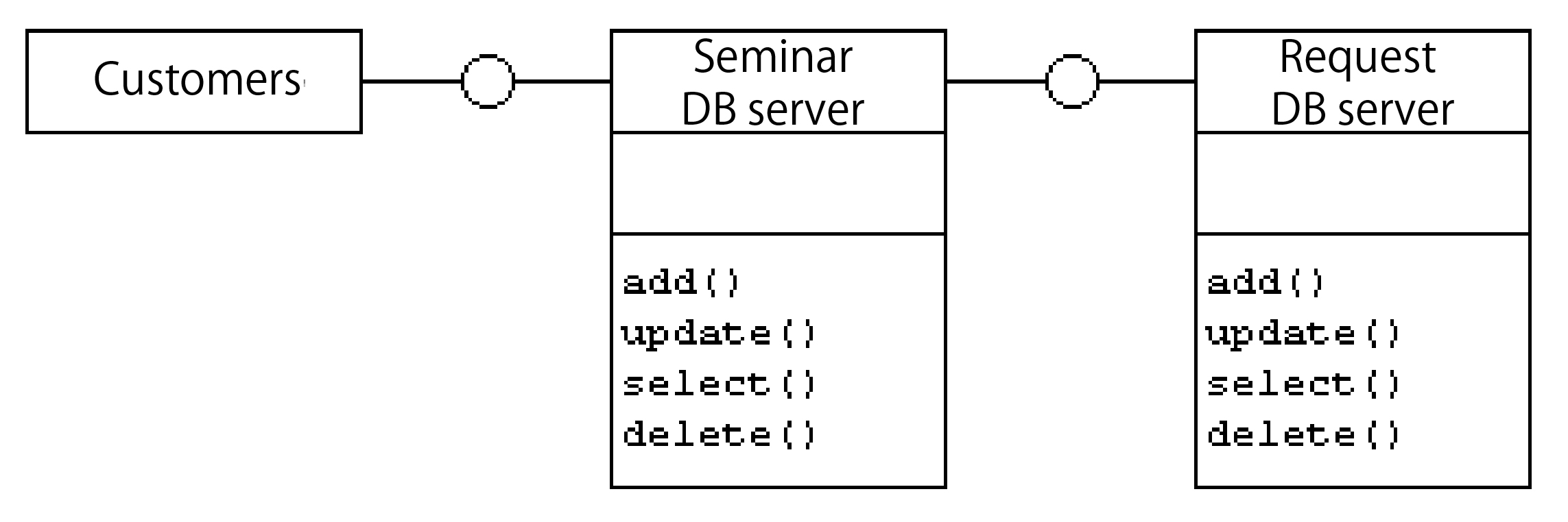
Since the type model is an abstracted model, assembly is not included. At the very beginning of the component design stage, assembly is taken into account. Here as shown in Figure 24, we design various types of components in Figure 21 as DB components. Represent the "seminar" type the "seminar application" type as the "seminar DB" and the "request" as "request DB". These components contain operations the equivalent to DB operations like "add ()", "update ()", etc. Due to the result of component design, you must return to the internal design stage to modify the type model.
Determination of system architecture
After the component design, we should decide the system architecture. Just like in the design stage, the two components "seminar DB" and "request DB" are included in the seminar management system. As shown in Figure 25, treat the "seminar DB" and "request DB" as independent applications. All of them will eventually be assembled in the form of CORBA, DCOM, EJB and other application servers.
Pattern and modeling framework
Next, we will have a brief description about the model framework of catalytic method. When the type model is finished, sometimes mode can be found during modeling. Speaking of software modes, it is easy to think of the design mode on the program level and the analysis mode on the analysis level. In the catalytic method, application mode can be adopted to achieve efficient modeling.
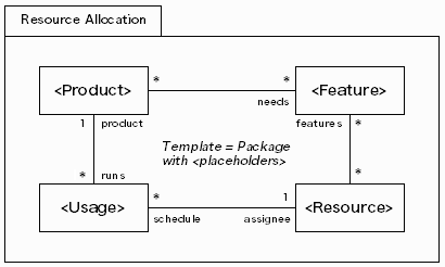
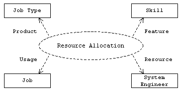
In the catalytic method, we call the mode which is usually adopted for model analysis "model". At the same time, "model framework" refers to something that models the object. Here we introduce the "Resource Allocation" template in the catalytic method (Figure 26). As shown in Figure 27, the model is applied to other models related to system engineers. We can replace <Product> with Job Type, <Feature> with Skill, <Usage> with Job, and <Resource> with System Engineer.
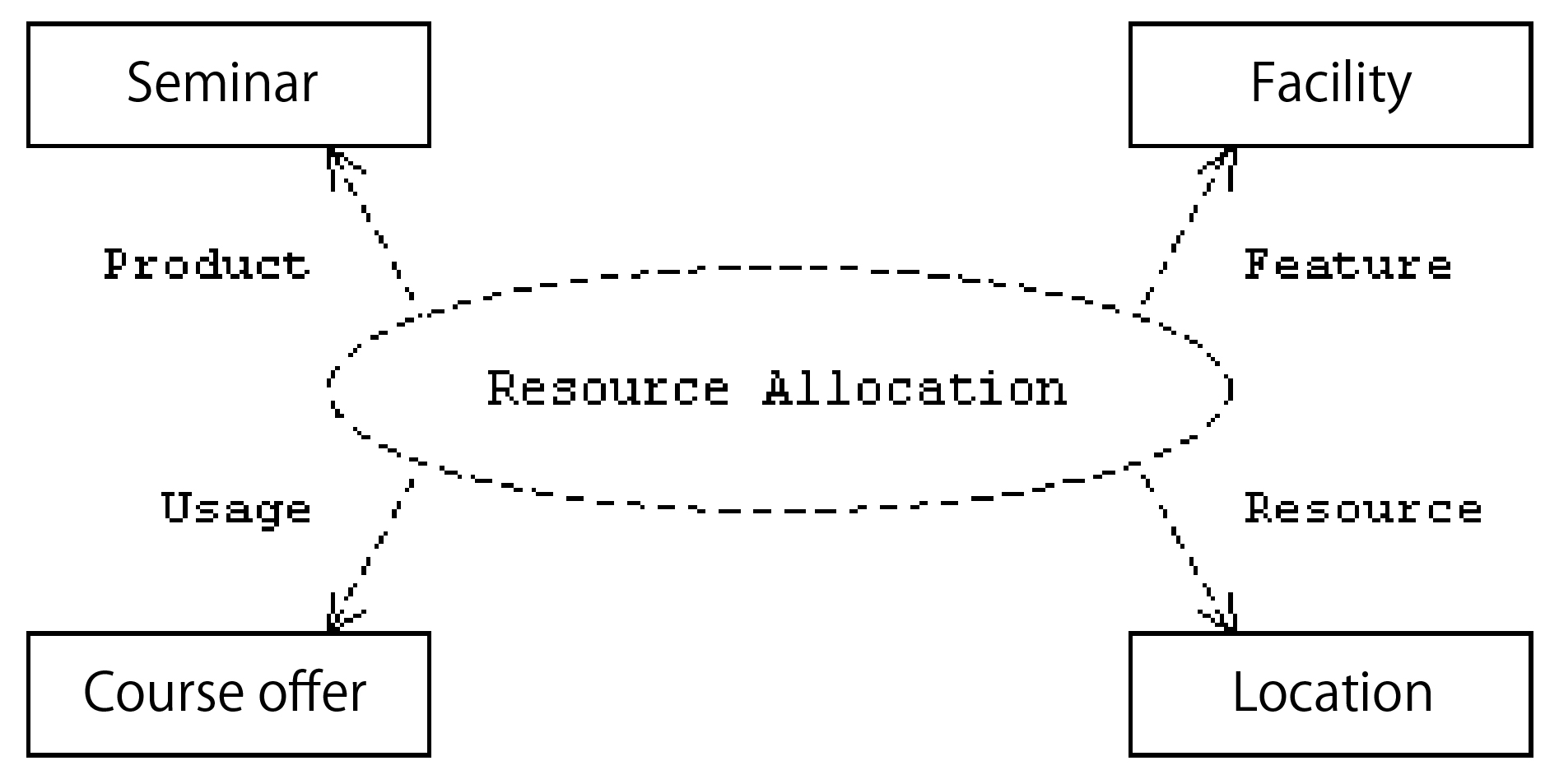
The Resource Allocation template is also applicable to the seminar management system. The result is shown in Figure 28.
Add the "Instructor". (Figure 29)
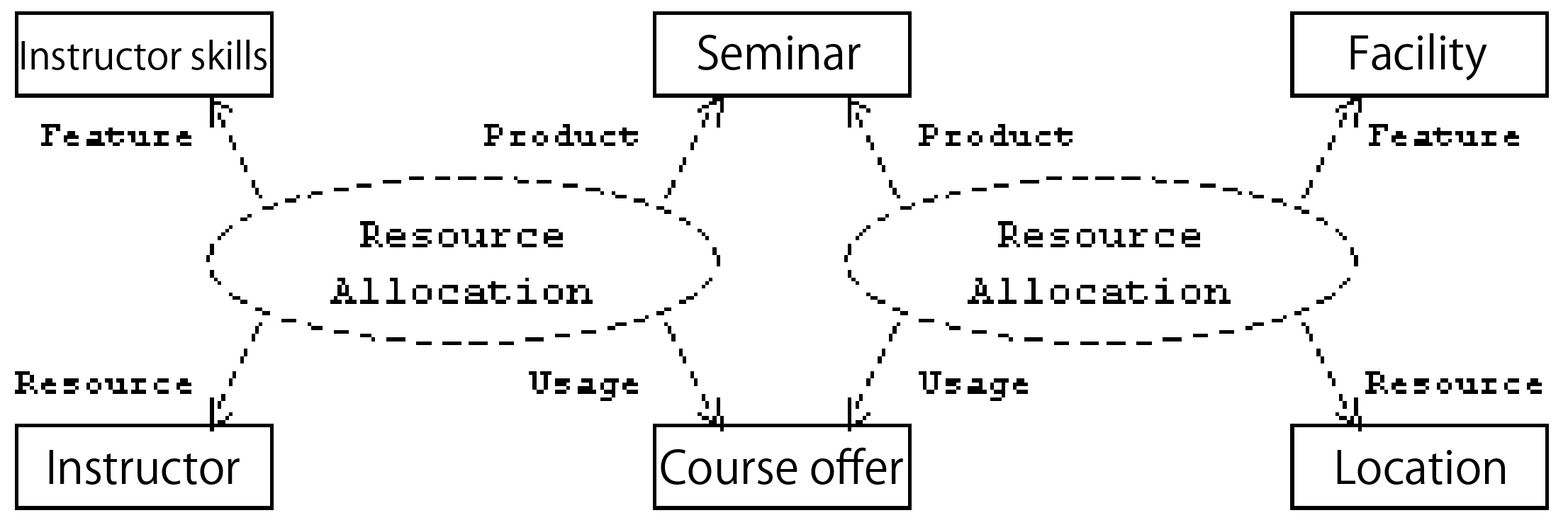
Compared with the model in Figure 28, the one in Figure 29 uses pattern again. Therefore, only by applying the pattern to the model can it be reused as model framework. In the design and assembly stage, the "Resource Allocation" has been completed as a framework. Since there are many application achievements, the productivity can be significantly increased through recycling.
Summary
We've completed the brief description about the catalytic method and want to hear your response. The adoption of systematic modeling methods can improve the production efficiency in the development. We shall be looking forward to your valuable suggestions on this point